| Sujet : RadioVox Nouveau | De PCB Le 02-01-2007 à 22:31 sta |
|
I must first appolgise for my lack of French, a reply in English would be very helpful.
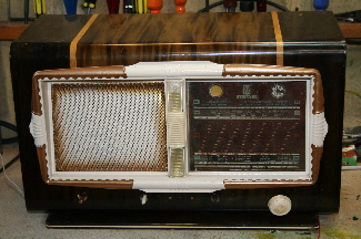
I have a RadioVox Radio (Alternatif) of about 1949-1952 age which I am restoring in England.
All the tubes (6) (valves) are pretty standard as follows ECH42, EF41, EBC41,EL42, EZ80(or EL80), EM4 I.F. frequency is 455kHZ
If anybody has a schema (circuit diagram) for this radio I would be most grateful
The RF stage is dead and a schema would make things a lot easier.
Many thanks and regards,
Peter Barton
|
|
| Sujet : RadioVox Nouveau | De ON5MJ Le 02-01-2007 à 23:21 sta |
|
Hi Peter,
A reply in English wouldn't be too difficult (at least in pidgin English). We even have French members living in the US.
By the way is there a type number or the like somewhere on this radio ? A picture would also be helpful.
If there is an EL42 there is probably no EL80. It was more usual to use an EZ40 or an EZ41 in this time instead of an EZ80. Eventually the rectifier tube should have been changed for repair.
Jacques.
|
|
| Sujet : RadioVox Nouveau | De JC Négret Le 03-01-2007 à 09:09 sta |
|
Is this one ? here ?
JC 
|
|
| Sujet : RadioVox Nouveau | De PCB Le 04-01-2007 à 00:35 sta |
|
Hi Jacques and JC,
The only other type mark is 'Alternatif ' written on the label at the back, and you are right the rectifier tube (I think redresseur in french) has been changed and was originally a EZ40 or EZ41.
JC is correct with his suggestion, my Radiovox is almost identical to the Radiovox Vendôme (1949)except it does not have the bits (scrolls) on the side and the base is slightly different. It has the four white knobs on the front and valves (tubes) are the same.
Now the question is, does any body have schema (Circuit Diagram) for the Vendôme or know where I can get one.
Thanks again for all your help,
Many thanks , Peter Barton
|
|
| Sujet : RadioVox Nouveau | De ON5MJ Le 04-01-2007 à 03:04 sta |
|
Hi Peter,
1. 'Alternatif' is probably a warning to the users, telling that this radio must be used on AC. In this time DC power outlets still existed and the transformer wouldn't have appreciated.
2. Following the link posted by Jean-Claude, the rectifier was rather a GZ40 than an EZ one. This is not too difficult to see: on the transformer there is a separate secondary winding that has a different heating voltage for the rectifier. The GZ40 is rated at 5V instead of 6.3V for the filament, 90 mA max for HT current and 50 µF max as the first capacitor.
3. Perhaps RadioVox has build different models with the same chassis and same wiring diagram. All the people didn't appreciate the side bits (called 'oreilles' = 'ears' in French).
4. I hope someone reading this topic will find a circuit diagram, but following my past experience this radio wouldn't be too difficult to repair, even without the paper. Nonetheless it requires that you have some basic experience and a few reference books. Keep us informed.
Jacques.
|
|
| Sujet : RadioVox Nouveau | De F6FKN Le 04-01-2007 à 13:46 sta |
|
If the supply valve is really and EZ80, the socket should be a noval one.
9 pins at about 30 degrees each, with a gap of about one pin, between pins #1 and #9.
If it is an EZ40 or 41, (Rimlock socket), all the pins are regularly spaced, (no gap) and you should find a small vertical groove on the side of the socket to guide the tube vhen you'll insert it.
We all hope you'll be successfull in restoring your old wireless set.
Alain
|
|
| Sujet : RadioVox Nouveau | De WB4ENI Le 04-01-2007 à 16:20 sta |
|
>>restoring your old wireless set<<
Tssk, tssk... People may be old (I know I am) and wines improve with age (so do I  ). But radios may be "vintage" or "antique", NEVER old. ). But radios may be "vintage" or "antique", NEVER old. 
Marius ![[:Hi:]](s12.gif)
|
|
| Sujet : RadioVox Nouveau | De F6FKN Le 04-01-2007 à 22:17 sta |
|
Well, it's only a point of view...
But I won't fight against you for a so slight difference between both our opinions.
So, I'll try not to say that again in the future, and just remember to use "antique" which seems to be the convenient word, instead of old.
But, anyhow, I don't think this will help a lot in restoring this antique radio.
Alain
|
|
| Sujet : RadioVox Nouveau | De JC Négret Le 05-01-2007 à 08:57 sta |
|
Hi Peter !
No circuit diagram found for the Radiovox. This was a small radio'builder, so no schema...
To help you, here is a standard diagram with the same tubes :
Regards
JC
| |
|
| Sujet : RadioVox Nouveau | De JC Négret Le 05-01-2007 à 08:58 sta |
|
Old or not ?
JC
| |
|
| Sujet : RadioVox Nouveau | De F6FKN Le 05-01-2007 à 09:55 sta |
|
Maybe old antique ?
|
|
| Sujet : RadioVox Nouveau | De JC Négret Le 05-01-2007 à 10:18 sta |
|
An other one :
( I like American radios )
JC
| |
|
| Sujet : RadioVox Nouveau | De PCB Le 05-01-2007 à 14:33 sta |
|
Wow, what a great response.
Thank you, to you all for the comments I shall from now on always refer to my Radiovox as an Antique or Vintage or is it maybe still just Old or a combination of all three. Seemed to spark off a few comments there.
On the point about the rectifier, it probably was originally a GZ40 (8 Pin) and had a pip on the
valve. The socket and valve must have been changed before I got it, because its now a GZ80 (9 pin)(noval) without the pip, but it works just fine giving about 250vdc to the HT line.
Also thanks to JC for the Diagram, it is probably very close to the original Radiovox set, the year is about right and the valves are the same (Except the GZ40). I will be making good use of this.
My only other query is that the two IF transformers seem to oscillate at about 1.2 Mhz instead of 445Khz is stated on the cans. Do they drift this much with age? Any thoughts.
Thanks again Peter
|
|
| Sujet : RadioVox Nouveau | De F6FKN Le 05-01-2007 à 15:41 sta |
|
First of all, in my knowledge, GZ80 does not exist. (More probably an EZ80)
But the filament voltage of the GZ40 (5V), is not really suitable for an EZ80 (6,3V)
So I'm afraid the voltage is a bit weaker than it should be.
Maybe you should perform a quick check to know the truth.
Secondly,a so huge drift is totally impossible, unless the internal capacitors have been removed or damaged.
Is it a self oscillation from your IF stage, or an out of range tuning from your IF transformer ?
It's possible to observe the output of the IF amplifier, near the detection plates with a correctly calibrated oscilloscope, to have a rough idea of which frequency you really have at the output of the IF amp.
Also check if the shields are correctly grounded.
Alain
|
|
| Sujet : RadioVox Nouveau | De ON5MJ Le 05-01-2007 à 16:43 sta |
|
Hello Peter,
> a so huge drift is totally impossible, unless the internal capacitors have been removed or damaged.
It could be an oscillation on the 3rd harmonic, couldn't ?
Controlling all the ground leads is essential as told by Alain.
By the way where are you located ?
Jacques.
|
|
| Sujet : RadioVox Nouveau | De Phil Le 05-01-2007 à 18:31 sta |
|
Hello !
I like this kind of drawings, if you have some other, I am taking.
Thank !
Phil,
| |
|
| Sujet : RadioVox Nouveau | De PCB Le 05-01-2007 à 22:29 sta |
|
Hello again,
Regarding the two IF transformers, I was trying to check them at work to see if they had drifted out at all. I did this with a RF generator and an oscilloscope connected in parallel. When I swung the frequency around they seem to peak at around 1.2 MHz (instead of 445KHz) this was a very strong signal and nothing around 455KHz. The silver mica capacitors seemed to be in good condition as did the coils. I then, perhaps not wisely unwound some of each coil to re-tune them to 455. This may have been a mistake. I now realise what may have happened. The RF generator or the oscilloscope may have been putting a load on the transformers and altered their peek oscillating frequency and given me a false reading, I am not really to sure.
So I may have to look out for a new set of IF transformers.
A final question, do they have to be tuned to 455 or can they be tuned to 472 or any other frequency? Why 455Khz?
I reply to Alain, I am near Poole on the south coast of England.
Thanks once more
Peter
|
|
| Sujet : RadioVox Nouveau | De ON5MJ Le 06-01-2007 à 00:52 sta |
|
455 was choosen as a world standard: between LW and MW and the frequency lust not be an harmonic of a LW or an aviation beacon (ADF). Beter to keep the factory settings as the oscillator has also been designed for this IF frequency (the variable capacitor couldn't fit to the band spreading). IF frequency, variable cap and oscillator self are always working together. There is a standard process for lining up an IF transformer, do you know how to ?
About the load of the oscilloscope, it has a capacitance (resistance is normally very high) but as it's a parallel capacitance this would rather decrease the frequency. Are you sure the ferrite screws inside the IF transformer is still there ?
Jacques.
|
|
| Sujet : RadioVox Nouveau | De F6FKN Le 06-01-2007 à 07:25 sta |
|
I agree with Jacques.
Due to the capacitive behaviour of your oscilloscope's probe when connected to the IF transformer, the resonant frequency can only be decreased.
There's probably something wrong in your measurements.
Did you perform the RF injection from your generator directly on the anode of the heterodyne tube, through a small and well isolated capacitor, or through one of the grids of this tube, which would be a far more suitable method of injection, with a lower level, but without capacitive overload from the IF transformer's input ?
Make the test with the weakest possible injection level from your generator.
If you overload the IF transformer, and by the way, the IF amplifier's tube, this could lead to strong distortion, that could explain the strange results you have already observed.
So, the trick for today: Make your measurements with a weaker signal, through a small capacitor, directly through one of the grid of the heterodyne valve.
Alain
|
|
| Sujet : RadioVox Nouveau | De PCB Le 06-01-2007 à 12:45 sta |
|
Thanks Jacques and Alain,
In answer to Jacques, yes, the ferrite screws are still there, and no I don't know the proceedure for linning up the IF transformers. If you have the process it would be very useful, thanks.
In Response to Alain, I performed the test on the IF transformers with them removed from the radio on the bench. I realise now that was not a good idea at all. As you say, I should have done the test on the IF transformers IN the radio. Now that I have probably destroyed the IF transformers by rewinding them I will probably have to get another set or rewind them again.
At least I know what I should have done. I should have asked you guys in the first place.
I will try and get a new set of IF transformers in the next week or so and use those.
Thank you both for all the information and I will send a new post when I get the new IF transformers fitted and let you know how it going.
Many thanks once again.
Peter
|
|
| Sujet : RadioVox Nouveau | De ON5MJ Le 06-01-2007 à 13:15 sta |
|
Hi Peter,
This is the point:
> Now that I have probably destroyed the IF transformers by rewinding them I will probably have to get another set or rewind them again.
This means that the self-inductance is quite lower than the original one, which brings the resonance to a higher frequency.
Do not try to rewind an IF transformer unless you are very skilled on this topics. Any building detail, including the gap between primary and secondary windings, is very important as the coupling must be optimised. The best would be to find another IF transformer set instead. IF transformers may not be swapped and even the order of lead connexion must be kept (plate, HT, grid, ground).
About the method of lining up this is the web link to the site of Jean-Claude Jardine but it's written in French.
http://perso.orange.fr/tsf/tsf/sh_rgl3.htm
Jacques.
|
|
| Sujet : RadioVox Nouveau | De Sylvain Vanier Le 06-01-2007 à 16:31 sta |
|
<In answer to Jacques, yes, the ferrite screws are still there, and no I don't know the proceedure for linning up the IF transformers. If you have the process it would be very useful, thanks.
In Response to Alain, I performed the test on the IF transformers with them removed from the radio on the bench. I realise now that was not a good idea at all. As you say, I should have done the test on the IF transformers IN the radio. Now that I have probably destroyed the IF transformers by rewinding them I will probably have to get another set or rewind them again.>
I have alignment procedures on my website if it can help. They are for Philco radios but apply to all makes. You,ll find the book here: http://www.oldradioz.com/technical_1 use the first Philco.djvu file (about 550k). The djvu browser is available also on my website in the technical/schematics section. Browse around, you will find tons of useful data, mostly on North-American sets though.
If you unwound the IF coil, by doing so it lowered the inductance thus raising the resonant frequency, as someone else suggested. Testing IF cans outside a radio is usually not a good idea simply because an inductor needs a capacitor to bring it into resonance and _sometimes_ the caps are outside the IF can. I will suggest a simple solution, before you actually go shopping for new IF coils. Add more capacitance in parallel, say between 100pf and 220pf on _both_ sides of the IF can (primary and secondary). The IF may not peak perfectly, or maybe it will, but it is worth a try.
Sylvain
|
|
| Sujet : RadioVox Nouveau | De ON5MJ Le 06-01-2007 à 16:54 sta |
|
Hi Sylvain,
Increasing the capacitance would be great if the original coils are unmodified since the coupling factor depends of it. Peter will never catch back the right bandpass and/or the symetrical shape. If Peter has unwinded the IF transformers, they will never operate properly. But it's OK just for a try. Experience is a cut and try process ....
You have a nice website. I was even surprised by your way to mold metal film resistors for the making of fake dog bone resistors. Just a pity that a few files exist only in djvu format : some people are reluctant to install the reader.
Jacques.
|
|
| Sujet : RadioVox Nouveau | De F6FKN Le 06-01-2007 à 20:35 sta |
|
If you send me the dimensions, the type, and a few photos from your IF transformers, with an without their shields, I can check inside my own stock of spare parts, just to see if, with a little bit of luck, I could find a couple of transformers which could do the trick.
But, for instance, I can't promiss anything yet.
Anyway, I'm almost certain I have some IF coils in perfect working order which could probably solve your problems, but I'll have to check my stock first.
Alain
|
|
| Sujet : RadioVox Nouveau | De PCB Le 07-01-2007 à 12:38 sta |
|
Alain, That would be very kind if you have any.
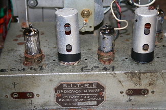
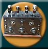
Here are the detail and photos
They are 3 cm in diameter
7 cm tall (hight)
2 cm between the solder tags (each way)
The writing on the can from top to bottom is
Bobinage
Omega
ISOTUBE
diode
455 kc/s
and on the other
Bobinage
Omega
ISOTUBE
rimlock
Tesla
455 kc/s
The tag on the top is where the board inside is supported through the can.
Sorry could'nt get the cans off, but I have included a photo of the radio so you can see what its like ........... without the 'oreilles'
Good luck in the search
Many thanks again
Peter
| |
|
| Sujet : RadioVox Nouveau | De ON5MJ Le 07-01-2007 à 13:43 sta |
|
I have the tech datas of those IF cans in fair resolution. If you want I can drop the two pages into your mail box provided you give it to me. Mine is on5mj (at) skynet dot be.
Jacques.
|
|
| Sujet : RadioVox Nouveau | De F6FKN Le 07-01-2007 à 17:43 sta |
|
Could you also drop them inside my mailbox too ?
It will be helpfull for me to find a suitable replacement for these transformers.
my call sign at wanadoo point fr.
Thanks
Alain
|
|
| Sujet : RadioVox Nouveau | De PCB Le 07-01-2007 à 21:56 sta |
|
Hi Jacques,and Alain,
Yes my email address is
pbarton(at)toucansurf.com
I shall look forward to having a look at them.
Best regards Peter
|
|
| Sujet : RadioVox Nouveau | De ON5MJ Le 07-01-2007 à 21:58 sta |
|
Hi Peter,
I have already sent the 2 pages to Alain. I will drop them right now.
Jacques.
|
|
| Sujet : RadioVox Nouveau | De ON5MJ Le 07-01-2007 à 22:07 sta |
|
My mail has been released. Bye and regards. - Jacques.
|
|
| Sujet : RadioVox Nouveau | De F6FKN Le 08-01-2007 à 22:15 sta |
|
I'll have some time to look for your pair of IF transformers next wednesday.
So, don't worry if you have no news from me till then.
Alain
|
|
| Sujet : RadioVox Nouveau | De PCB Le 08-01-2007 à 22:30 sta |
|
|
|
|

 Journaux du site au 22/08/2022 à 10:26